HALF ADDER
Half adder
is like a small circuit that performs an addition tasks on only two inputs 0
and 1 for each input and gives us two outputs one is sum and the second is
carryout number. Which consist of and exclusive OR gate that and AND gate
including two inputs, where X-OR gate perform Sum and AND gate gives carry out
number, which is more explain by logic diagram, logic symbol and truth table.
LOGIC DIAGRAM

half adder logic diagram

LOGIC SYMBOL:
 |
| halfadder logic symbol |
TRUTH TABLE
A
|
B
|
AÅB
|
A x B
|
0
|
0
|
0
|
0
|
0
|
1
|
1
|
0
|
1
|
0
|
1
|
0
|
1
|
1
|
0
|
1
|
FULL ADDER
Process is
same like half adder that perform addition and full adder also perform addition
where the main difference between them is the number of input, where half adder
have only two input and full adder have three inputs A, B and Cin. It also has
two outputs one is sum and second is carryout number. See the logic diagram,
logic symbol and truth table for understand to deep.
LOGIC SYMBOL
 |
| fulladder logic diagram |
In this series three inputs are A, B and Cin where the final
results are Sum and Carryout number as shown in figure. In full adder we used 5
gates two AND gate two XOR gate and one OR gate.
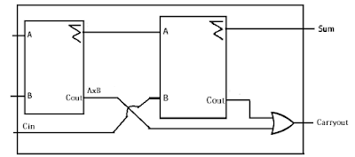
LOGIC SYMBOL
Arrangement
of two half adder to form a full adder in such a way that it look like as show
 |
| full adder logic symbol |
TRUTH TABLE
Inputs
|
Outputs
|
|||||||||||||||||||||||||||||||||||||||||||||
|
|


0 comments:
Post a Comment
Please do not enter any spam link in the comment box